
This was a fairly simple retrofit, with the biggest part required being the replacement rear bumper. I took the opportunity to upgrade to a facelift rear bumper and diffuser, which came with sensors and sensor loom. This was on my 2007 V6 TT.
Note: this guide covers fitting an early module (part numbers ending 283, the later ones 475). Early modules are on address 76 and use the convenience CAN, compared to 10 and the powertrain CAN for the later ones. I believe the changeover was in late 2008, so before the facelift happened.
Parts required:
Wiring
Since the bumper came with the sensor loom, I didn't have to make that up and I could simply plug it in the new module. The easiest way to tap into the convenience CAN is into the central convenience control module, which is also convenient in its location just under the parking module.
The permanent live feed is taken from the boot fusebox. The drivers sill trim pulls firmly upwards and is only clipped in. The rear seat bench should also be pulled up and removed along with the drivers side boot trim (requiring the rear boot trim, parcel shelf, boot floor and boot foam). This should give plenty of access to run the wires.
I wrapped all my wires in cloth tape and cable tied them to prevent rattles.
Park assist control module connector (A) (T16e) (16-pin)
Pin 1 > Fuse 7 in dash fuse box (5A) (positive, ignition live)
Pin 2 > Buzzer, pin 2
Pin 3 > Fuse 5 in boot fuse box (5A) (positive, permanent live)
Pin 7 > Central convenience control module block C, pin 10 (convenience CAN low - orange/brown wire) (already in use, need to splice) *
Pin 8 > Earth
Pin 10 > Buzzer, pin 1
Pin 14 > Central convenience control module block C, pin 9 (convenience CAN high - orange/green wire) (already in use, need to splice) *
Wired to dashboard fuse box for ignition live:

Spliced into convenience CAN (brown and green wires):

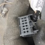
Connector wired up:

Ready to connect:

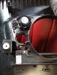
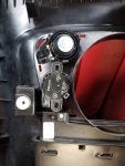
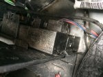
The module can be seen here on the right with the brown connector. The fuse tap for permanent live can also be seen:

The buzzer mounts into the rear right speaker area, seen below the tweeter here:

And from the front (with the speaker grille removed):

Coding
19-CAN Gateway - Installation List
76-Park Assist
Coding:
Note: 10-Park/Steer Assist uses long coding
You will now be able to adjust the volume and frequency in the DIS:


Note: this guide covers fitting an early module (part numbers ending 283, the later ones 475). Early modules are on address 76 and use the convenience CAN, compared to 10 and the powertrain CAN for the later ones. I believe the changeover was in late 2008, so before the facelift happened.
Parts required:
Code:
4H0 919 275       | Ultrasonic parking sensor x4
1T0 919 133 C 9B9 | Sealing rings (satin black) x4 (also available in other colours)

8J0 971 085 D     | Loom for parking sensors x1
     or
3C0 973 203       | 3 pin connector (for sensors) x4
8E0 972 112       | 12 pin connector (for control module) x1

8E0 972 416 A     | 16 pin connector (for control module) x1
000 979 009 E     | Wire set with square pins x4 (7 pins)

8P0 919 283 D     | Park assist control module (J446) x1

8E0 919 279       | Buzzer x1
4B0 972 623       | 2 pin connector (for buzzer) x1
000 979 009 E     | Wire set with square pins x1 (2 pins)

000 979 009 E     | Wire set with square pins (for central convenience control module marked * below) x1 (2 pins)
                  | Piggy back blade fuse holder with 5A fuse x1
                  | Piggy back mini blade fuse holder with 5A fuse x1

                  | Wire - 0.35mm² thin wall
| Eyelet ground terminal x1Since the bumper came with the sensor loom, I didn't have to make that up and I could simply plug it in the new module. The easiest way to tap into the convenience CAN is into the central convenience control module, which is also convenient in its location just under the parking module.
The permanent live feed is taken from the boot fusebox. The drivers sill trim pulls firmly upwards and is only clipped in. The rear seat bench should also be pulled up and removed along with the drivers side boot trim (requiring the rear boot trim, parcel shelf, boot floor and boot foam). This should give plenty of access to run the wires.
I wrapped all my wires in cloth tape and cable tied them to prevent rattles.
Park assist control module connector (A) (T16e) (16-pin)
Pin 1 > Fuse 7 in dash fuse box (5A) (positive, ignition live)
Pin 2 > Buzzer, pin 2
Pin 3 > Fuse 5 in boot fuse box (5A) (positive, permanent live)
Pin 7 > Central convenience control module block C, pin 10 (convenience CAN low - orange/brown wire) (already in use, need to splice) *
Pin 8 > Earth
Pin 10 > Buzzer, pin 1
Pin 14 > Central convenience control module block C, pin 9 (convenience CAN high - orange/green wire) (already in use, need to splice) *
Wired to dashboard fuse box for ignition live:
Spliced into convenience CAN (brown and green wires):
Connector wired up:
Ready to connect:
The module can be seen here on the right with the brown connector. The fuse tap for permanent live can also be seen:
The buzzer mounts into the rear right speaker area, seen below the tweeter here:
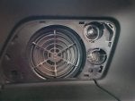
And from the front (with the speaker grille removed):
Coding
19-CAN Gateway - Installation List
- 283 modules - Enable '76 - Park Assist'
- 475 modules - Enable '10 - Park/Steer Assist'
76-Park Assist
Coding:
- 00?xxxx: Trailer Hitch
0 = Trailer Hitch not installed
1 = Trailer Hitch installed - 00x?xxx: Transmission
0 = Manual Transmission
1 = Automatic Transmission - 00xx?xx: Specification
0 = Rest of World (RoW)
1 = Rest of World (RoW) S/RS
2 = North America (NAR)
3 = North America (NAR) S/RS - 00xxx?x: Chassis
0 = Sedan
1 = Avant (Wagon)
2 = Cabriolet
3 = Coupé
5 = Sports Car (R8 only) - 00xxxx?: Model
1 = Audi TT (8J) / Audi R8 (42)
3 = Audi A3 (8P)
Note: 10-Park/Steer Assist uses long coding
You will now be able to adjust the volume and frequency in the DIS: