Audi TT Forum banner

Retrofit: Reversing Camera with OPS

55K views 369 replies 16 participants last post by  MT-V6  
#1 · (Edited)
Following from my previous retrofit of front and rear parking sensors with OPS I have now got the full R8 system functioning, which includes a reversing camera with moving guidelines as well as reverse parking and parallel parking modes.

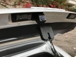
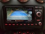
Initial test fit with messy wires resulting in poor image quality, but a good enough indicator to continue:

Parts

8V0 827 566 - Camera (from Audi A3 8V)
4G5 827 229 - Camera bracket
6mm SBR rubber sheet
M6 sleeve nut x2
M10 4mm heavy washer x2
M10 spring washer x2

1J0 973 119 - 2 pin connector for camera power
000 979 019 E - Pins (micro timer) x2
Female FAKRA Z to female RCA adaptor

1J0 973 119 - 2 pin connector for boot button
000 979 019 E - Pins (micro timer) x2
000 979 009 E - Pin for central convenience module

420 910 441 A - Camera module supporting OPS (from Audi R8 42)
4E0 972 144 - 54-pin connector
TE 2-1411550-1 - Pins (ELO) x15
Female right angle FAKRA Z to female RCA adaptor
EVA high density foam to secure the module

N 907 327 03 - Pin for fuse (Standard Power Timer)
000 979 009 E - Pins for RNSE 32 pin connector (MQS) x6
Male RCA connector

Wire 0.35mm2
Wire 8 core 0.22mm2 screened stranded

Fitting

The feeding of wires is covered in other places, including this comprehensive post, so I'll skim over that here.

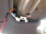
Firstly, there is no 'official' mounting location for the camera module, so I chose to position it behind the right boot trim near the parking sensor module. Wires need to be be run in two directions, (1) to the RNSE and (2) to the camera in the tailgate.

8.jpg


(1)

I have documented how I fed my parking sensor wires through the car in the past, see this guide for some photos https://www.ttforum.co.uk/forum/viewtop ... &t=1837385

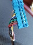
I used 8 core 0.22mm2 screened stranded cable for the video feed:

4.jpg


The connector wired up (with outer housing removed):

5.jpg


I used screw terminal RCA connectors, with Fakra adaptors on both ends.

The module fitted in the spare space near the convenience/PDC modules. I used some EVA high density foam on the left to hold it firmly in place:

20200411_124033.jpg


(2)

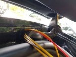
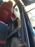
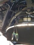
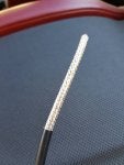
Feeding the wires to the camera is a pain but not too bad. With the tailgate trim and boot trim removed, use a thick wire to help feed the wires up the C pillar, through the right grommet, down the rear screen and eventually to where the number plate lights are mounted.

1.jpg


2.jpg


3.jpg


In order to mount my camera, I needed to cut a rectangular opening in the tailgate. A daunting prospect but it gives a neat OEM finish.

6.jpg


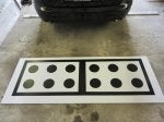
Due to the tailgate lip, it needs to be spaced out slightly. I used 6mm thick SBR rubber sheet to make a gasket for the camera:

20200624_183816.jpg


Because of the gasket, the standard nuts will no longer reach the thread, so I used spacers, spring washers and sleeve nuts:

20200530_192721.jpg


The result is a good clear image without too much obstruction:

20200531_155246.jpg


20200605_104314.jpg


Wiring

Reversing camera system control unit (J772) - (54-pin connector, black)
Pin 25 > RNSE (T32b), pin 14 (screen earth)
Pin 27 > RNSE (T32b), pin 15 (video output sync)
Pin 28 > RNSE (T32b), pin 30 (video output sync earth) (splice all RGBS earths together)
Pin 29 > RNSE (T32b), pin 31 (video output blue)
Pin 30 > RNSE (T32b), pin 30 (video output blue earth) (splice all RGBS earths together)
Pin 31 > RNSE (T32b), pin 16 (video output green)
Pin 32 > RNSE (T32b), pin 30 (video output green earth) (splice all RGBS earths together)
Pin 33 > RNSE (T32b), pin 32 (video output red)
Pin 34 > RNSE (T32b), pin 30 (video output red earth) (splice all RGBS earths together)

Pin 39 > Infotainment CAN low (splice Bose amp T32a pin 32 - orange/brown)
Pin 40 > Infotainment CAN high (splice Bose amp T32a pin 27 - orange/purple)

Pin 43 > Fuse 5 in boot fuse box (5A) (positive, permanent live)
Pin 44 > Terminal 31 (earth)

Pin 47 > Camera power connector, pin 2 (earth)
Pin 48 > Camera power connector, pin 1 (positive)
FAKRA ground > Camera phono (ground) (black)
FAKRA signal > Camera phono (signal) (yellow)

Camera module.png


Camera power connector - (2-pin connector, black)
Pin 1 > Reversing camera system control unit, pin 48 (positive)
Pin 2 > Reversing camera system control unit, pin 47 (earth)

Rear lid handle release button
The boot handle is also functional, which is a bonus, due to modules being shared with the A3.

Pin 1 >
  • Pre ~2009 cars with J393 central convenience module > T8g, pin 6
  • Post ~2009 cars with convenience module combined with J519 central electric (BCM) > T52a, pin 13
Pin 2 > Earth point inside tailgate

Coding

19-CAN Gateway - Installation List
  • Enable '6C - Back-up Cam.'[/*]

10-Park/Steer Assist - Coding
  • Byte 0, bit 5 - enable 'Rear View Camera installed'[/*]

37-Navigation
  • Adaptation:
    • Channel 04: Rear View Camera
      • 3 = Rear View Camera (BAP/RNS-E PU) installed[/*]
    • [/*]
  • [/*]

6C-Back-up Cam.
  • Coding:
    • ?xx0xxx: Manufacturer
      • 1 = Audi[/*]
    • [/*]
    • x?x0xxx: Market
      • 0 = Rest of World (RoW)[/*]
    • [/*]
    • xx?0xxx: Trailer & Parking System
      • +2 = Optical Parking System installed[/*]
    • [/*]
    • xxx0?xx: Camera Height
      • 7 = Camera Height 8 (+70 mm)[/*]
    • [/*]
    • xxx0x??: Model
      • 12 = Audi R8 (42) with Standard Camera Height 665 mm[/*]
    • [/*]
  • [/*]

Calibration

< WORK IN PROGRESS >
 
  • Like
Reactions: Barr_end
#5 · (Edited by Moderator)
I started to tidy the wires today, starting with the tailgate, and especially the grommet to the body of the car. I chose the right side as it felt like there were fewer wires already in it, and I will also be mounting the reverse camera module on the right near the existing PDC module. It wasn't as bad as I'd expected.

After removing the boot trim, I used thick wire to feed through the grommet, with the other wires taped to it. Seen here emerging from the grommet is the thicker yellow wire, with smaller white, grey, black and yellow wires. Then I fed a thick red wire into the car body, taped the above thick yellow wire to that and pulled the lot through.

20190916_151202.jpg


Thick wires emerging above the headlining.

20190916_151217.jpg


I didn't take more photos for now, but I removed the thick wires and cloth taped the 4 smaller ones.

Next I will feed it behind the C pillar into the right side of the boot where I will mount the module. Waiting for a couple of connectors to arrive, a phono one for the camera composite wire and a DC one for the camera power, as I have used my own custom length cables for this rather than the supplied one.
 

Attachments

#7 ·
Yep, compared to the aftermarket media adaptors that kind of replicate a TV module. As usual I'll list all the parts once I've finished as well as a rough guide
 
#8 · (Edited by Moderator)
A bit of preparation as I start to wire this in properly. My camera has optional gridlines, which are disabled by connecting 2 green wires from the camera. I soldered them together, heatshinked them, then wrapped the lot in cloth tape to prevent rattles in the tailgate.
20190918_221323.jpg


I left a little bit of green exposed to remind me in future where those wires are!
20190918_221714.jpg


Finally, I got a couple of screw terminal plugs for the composite RCA and the power connector (2.1mm x 5.5mm DC connector)
20190918_221825.jpg


Also going to fit LED bulbs in this as I've had to remove my LED sealed unit number plate lights for the camera. Need some that are error free, think I will try these are the reviews are positive https://www.autobulbsdirect.co.uk/239-t ... -bulb.html
 

Attachments

#9 · (Edited by Moderator)
I made good progress over the weekend.

The camera end of the loom with power and RCA connectors:

20190919_124122.jpg


Firstly fed the camera loom down the right C pillar (the thick red wire seen here was to poke my loom through). I attached my new loom to the existing cable brackets to stop it rattling:

20190920_121828.jpg


At this stage, this ends by the PDC module.

Next was to run signal wires from the same location to the RNSE. The wiring diagrams show that 9 are required: Red, Green, Blue and Sync, individual earths for all of those, and Screen. For this I used 8 core 0.22mm2 screened stranded cable, which worked well and was fairly simple to work with.

The cable outer insulation removed, showing the braided screen:

20190921_120428.jpg


The screen was unwound and twisted, and soldered to a short length of the usual 0.35mm2 wire I use (in this case grey). It can be seen here with the heat shrink wrap in the module connector:

20190921_132346.jpg


I then added the extra wires to the module connector (module positive and earth, infotainment canbus high and low, camera positive and earth. Also the camera signal wires are terminated with an RCA connector (more on this later):

20190921_143204.jpg


I ran the wire to the RNSE in exactly the same was as I did for the front parking sensors, which I have documented already so I won't go through it again, but for those who missed my thread for that, see here https://www.ttforum.co.uk/forum/viewtop ... &t=1837385

The modules video input is via Fakra, so I used a Fakra to RCA adaptor lead like this:

s-l1600.jpg


The wires are connected to the RNSE 32 pin connector in a similar way as the module connector, that is the screen is unwound, twisted, soldered and heat shrinked. However, at this end, the 4 individual RGBS earths are joined. I twisted them and soldered them to a short length of wire in the same way as the screen. No photos of this yet but will try and get some soon.

Now, excited to try it all out, I connected the module, turned out the ignition and pressed the parking button, and... nothing! Parking sensor beeps but no camera or even OPS. I plugged in the laptop, cleared fault codes caused by unplugging various things, but still no luck. A video input fault code recurred (the camera), so I then I had a look at the reversing camera module measuring blocks when I noticed something odd. The module only puts out ~6v to the camera.

Since I am not using an OEM camera, which presumably runs on 6v, my aftermarket camera wasn't getting enough voltage to work. When I test fitted previously, I powered the camera directly with 12v. I temporarily powered it directly again and it's all good, so I need to use a relay after all to power this, or else investigate an OEM option.

More good news is that the image quality is much better now the wiring is tidy, unlike in my previous video. For now, a couple of photos (still using the A3 OPS graphic for some reason, and the camera not clipped in straight).

Parallel parking mode:

20190922_184438.jpg


Reverse parking mode:

20190922_184458.jpg
 

Attachments

#11 ·
MT-V6 said:
Since I am not using an OEM camera, which presumably runs on 6v, my aftermarket camera wasn't getting enough voltage to work. When I test fitted previously, I powered the camera directly with 12v. I temporarily powered it directly again and it's all good, so I need to use a relay after all to power this, or else investigate an OEM option.
I was informed that most manufacturers OEM cameras are 6v, which makes sense based on my findings, so I did use the relay method in the end, though the wiring still needs work.

I wired the relay coil to the camera module 6v output, with the 12v supply currently ignition live.

This works fine, but not for long. I suspect the aftermarket camera isn't liking being constantly powered as it appears the OEM ones do.

My next plan is to forget the camera module 6v output altogether and wire the relay coil to the reverse light feed, in the same was the aftermarket RNSE multimedia adaptors usually are (like in the main thread on this forum)
 
#12 ·
I believe the image quality depends on the display screen more than the camera. Most camera's can produce an image quality better than the RNS-E screen can support. My 2007 has the early RNS-E and the image quality is shite, especially in low light conditions. Later models have better screen resolution, but still not stellar.

Early RNS-E's have around 400x240 resolution, while the later models have 800x480. I am open to correction as this is off the top of my head. :)
 
#13 ·
I am actually pretty happy with the quality, more than good enough for a reverse camera. I need to run the calibration to hopefully straighten the image perfectly

I also realise I cannot use the reverse light feed as I mentioned above as the parking system can be triggered when the car is in any gear below ~10mph. Instead I am going to use the parking button LED light to trigger the relay
 
#14 · (Edited by Moderator)
Current setup is to use the PDC status light to trigger the relay, to provide 12v to the camera.

However, this still isn't working reliably, and I can only assume it's because the module expects the camera to be permanently powered, and the delay in getting the video feed when in reverse is causing the module to error.

My latest idea to to try to remove the camera from the equation to narrow down the fault. I have temporarily wired in a little converter that outputs a 'no signal' image when nothing is connected, and I tested this on a TV indoors and it was still outputting after several hours.

I fitted this today and I did get the image, but for some reason it disappeared from the RNSE after a few minutes to never return. Hopefully I'll have better luck after a full ignition cycle overnight.

Interestingly, the camera module/RNSE is distorting the image to give the fisheye effect:
20191111_180749.jpg
 

Attachments

#15 ·
I have now wired up a genuine Audi camera, and it works properly. I'm still unsure as to what the genuine camera does differently to the aftermarket camera and video converter box? Can the composite output be different somehow?
 
#16 · (Edited by Moderator)
I now have the TT graphic back. Not completely dure how, but the only change I've made in a while was to switch the RNSE to use the TT startup screen (I didn't realise I didn't have this set). Still, that would be weird if it used a different coding to the OPS sensors only, so I suspect it's more to do with unplugging/resetting things as I've been trying things out

20200118_103703.jpg


I also have another OEM Audi camera which is also working properly, but hopefully I'll be able to get this one mounted in the tailgate. More updates to come
 

Attachments

#17 ·
I'm wondering if this will work on an aftermarket head unit or does the graphic depend on RNSE as well?

Looks like all the connections made so far are regular video and power. But then does the wiring for the r8 modules go into the RNSE too?
 
#18 ·
The graphics are done by the RNSE, over canbus. I imagine maybe the video is would work but not sure of the benefit over just a composite camera for aftermarket head units?
 
#20 ·
Hmm, not sure where that is added

I think the camera module does have measuring blocks for steering angle bit I don't know where the overlay is added
 
#23 ·
I originally fitted the same as SJP above, however that's the camera I had issues with. Then I wired an OEM A6 camera as that's what the A3 8P people fit, but it's a lot easier to mount on their cars. However, it confirmed I'd wired and coded it all property

Now I have an A3 8V boot handle camera, which again works properly but should in theory be a bit easier to fit. So no proper photos fitted as yet but I will at some point. This is definitely one of the more drawn out retrofits I have done, but I really want it looking completely OEM!

As for the slight offset angle SJP, o e wired up the module can be calibrated which should skew the image to correct for the placement. Many OEM cameras are offset too. O hope to document it all when I get on to it, though weather at this time of year isn't ideal
 
#24 ·
I have test wired the A3 8V camera now and it works correctly. Also interestingly the handle switch can be wired to the convenience module to operate the boot popper, in the same way as on the A3 itself. I was unsure if it would work as the convenience module, although similar, isn't shared with the A3

The handle works by grounding convenience module pin D6, so very simple. Was a pain having to rerun an additional wire to the tailgate though!

Photos will eventually come once fitted
 
#26 · (Edited by Moderator)
MT-V6 said:
As for the slight offset angle SJP, o e wired up the module can be calibrated which should skew the image to correct for the placement.
If you know how to make the adjustment to correct the off-set, please let me know. That would be very helpful. Especially for those of us who did manage to install this particular camera. :)

I found this link for a reverse camera calibration (not for a TT) and wondered if the method can be used. Since the RNS-E can be set for a reverse camera, I would assume there's a camera calibration setting somewhere in there too??

https://www.audizine.com/forum/showthre ... alibration

CamCal.JPG

CamCalVCDS.JPG


From Ross-Tech (http://wiki.ross-tech.com/wiki/index.php/Audi_Q7_(4L)_Back-Up_Camera#Special_Procedures)

Audi Q7 (4L) Back-Up Camera
(Redirected from Audi A4 (8K) Back-Up Camera)
Contents
1 Coding
2 Security Access
3 Special Procedures
3.1 Back-Up Camera Calibration
Coding
?0x0xxx: Manufacturer
1 = Audi
x0?0xxx: Trailer & Parking System
+1 = Trailer Hitch installed
+2 = Optical Parking System installed
x0x0?xx: Camera Height
0 = Camera Height 1
1 = Camera Height 2
2 = Camera Height 3
3 = Camera Height 4
4 = Camera Height 5
5 = Camera Height 6
6 = Camera Height 7
7 = Camera Height 8
x0x0x??: Model
01 = Audi Q7 (4L)
02 = Audi A8 (4E) Short Wheel Base
03 = Audi A8 (4E) Long Wheel Base
04 = Audi A6 (4F) Sedan / Rest of World (RoW)
05 = Audi A6 (4F) Wagon/Avant
06 = Audi A4 (8K) Sedan
08 = Audi A5 (8T) Coupé
12 = Audi R8 (42)
14 = Audi A6 (4F) Sedan / China (CHN)
Security Access
22351 = Adaptation Enabling (e.g. Back-Up Camera Calibration)

Special Procedures
Back-Up Camera Calibration
After performing service work, the calibration has to be performed too. In detail this is the case after:

Removing and Installing Rear View Camera (R189)
Replacing Rear View Camera System Control Module (J772)
after repair work performed on rear lid following an accident
after a vehicle alignment
after performing a repair at front or rear axle
Prerequisites:

Calibration Device (VAS 6350) and Distance Laser (VAS 6350/2) positioned as described in the factory repair manual.
Vehicle must be standing on a firm and even surface.
Make sure no persons are being/working in/on the vehicle while performing the calibration.
Do not move the vehicle and do not operate the vehicle doors while performing the calibration.
Rear Lid must be closed.
Front Wheels straight, Steering Angle Sensor (G85) close to 0.0 °.
Ignition must be ON, Engine must NOT be running, you may connect a charger to keep the system voltage up.
Back-Up Camera active and the MMI shows Back-Up Camera Video Signal.
Make sure you do NOT have light reflections on the Calibration Device (VAS 6350).

NOTE: VAS 6350 Info can be found here -
https://workshop-manuals.com/audi/a4_mk ... tvas_6350/

For vehicles with Level Control, set the Hight to automatic.

[Select]
[6C - Back-Up Camera]
[Security Access - 16]
Enter 22351, to enable the adaptation.
[Adaptation - 10]
Channel 005
[Read]
500 mm is the basis value of channel 005. Measure the heights between the Calibration Device (VAS 6350) and the surface (e.g. 80 mm), add 500 mm to it and enter the final value as new value (e.g. 500 + 80 = 580 mm).
[Test]
[Save]
Channel 004
[Read]
20000 mm is the basis value of channel 004, 3002 mm (wheelbase for Audi Q7 (4L)). Measure the Distance between the Calibration Device (VAS 6350) and the rear axle (e.g. 1500 mm), and subtract it from 20000 mm minus 3002 mm enter the final value as new value (e.g. 20000 - 3002 - 1500 = 15498 mm).
[Test]
[Save]
Channel 001
[Read]
To save your above adaptation save a new value of 1 to channel 001.
[Test]
[Save]
[Done, Go Back]
Now double check the calibration status.
[Meas. Blocks - 08]
Block 130
[Go!]
Block 130 Field 3 (Calibration Status)
Specification: 0x0000 (Calibration Successful)
[Done, Go Back]
[Close Controller, Go Back - 06]
 

Attachments