I used a VPN (Proton VPN) to simulate USA and it worked. I actually use the VPN quite often in order to access the
LLLParts website.
Here's the entire article. Sure hope this helps. I also attached the entire article as a PDF which is located at the bottom of this thread if you want to download it.
Update: This post might also be helpful -
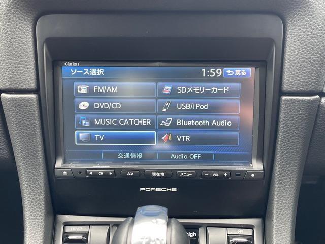
981 Forum - Japan market 981 Cayman - replacement audio - I have a Japan market 2014 981 base cayman. Japan specification 981 Cayman's don't have a Porsche PCM for audio, they have a Clarion Navigation system fitted as OEM equipment. My car has the standard factory 2014 Clarion Navi still...
rennlist.com
Good luck!
🤞
Replacing Japanese Clarion for RNS-E
STEP 1 -
The original navigation system for my 2012 TTRS has finished updating its map and does not show the closest interchange on the Ken-O Expressway from my house, so I replaced it with the final model original navigation system for the TT (8J) that shows this interchange.
However, the one I got on Yahoo! Auctions is for the A3, and the Audi model number is J8PAE2JP7, which is one letter different from the original J8JAE2JP7 for the TT, but judging from the shape, it seems like it can be installed by replacing the frame around the face of the navigation system. To remove the existing navigation system, insert a special tool into four places and pull it out when the lock is released.
The navigation system I removed has the Audi model number J8JAE2AO5 and seems to be equivalent to Clarion's SD navigation system NX710?
By the way, the navigation system I'm replacing seems to be equivalent to NX712?The face of the navigation system has a TT frame bolted on (two on one side, as indicated by the red arrows, and one on the other side, for a total of four), so when I removed this frame and attached it to the A3 navigation system I had obtained, I found that the bolts and the positions of the top and bottom tabs were all the same, so it seems to be compatible as expected!
View attachment 532642
STEP 2 -
Pull out the navigation system and check the existing wiring. There were four major differences between the wiring on the back of the navigation system and the navigation system
being replaced.
1. The power connector on the existing navigation system is 20 pins, but the replacement navigation system is 18 pins.
2. The existing navigation system has a separate vehicle speed signal connector, but the replacement navigation system has this integrated into the power connector.
3. The antenna wire input to the existing navigation system is a connector, but the replacement navigation system has a plug.
4. Is there no place to connect the blue wire (red arrow) on the existing navigation system to the power connector on the replacement navigation system?
View attachment 532643
STEP 3 -
The power connector of the navigation system to be replaced is 18-pin, so I obtained the corresponding connector separately. If I knew the wire to connect, I could just cut off the existing connector and connect it, but since the navigation system
I obtained was a used product, I decided to keep the original 20-pin connector and purchase a new 20-pin female connector and connect it to the 18-pin connector to convert it so that I could restore it in case of any malfunction. This photo also shows the antenna return cord (for Honda cars) combined. The blue wire, which is thought to be the wire to the amplifier in the problem in ④ of Photo 2 above and has an unknown connection destination, was "branched" from the antenna power line from the navigation system, thinking that it would be fine as long as it
supplied power. I would have liked to use a female connector to connect the connector for the vehicle speed signal (speed, reverse, parking) that was input to the existing navigation system, but I was unable to find the corresponding female connector, so I had no choice but to use a one-touch connector to take the speed and reverse signals, and grounded the parking signal to the body of the navigation system to cancel the TV
View attachment 532644
STEP 4 -
Use the conversion connector made in photo 3 above to wire the replacement navigation system and the existing connector from the vehicle.
The blue wire that seems to be the problem amplifier wire was not connected to the 20-pin female coupler that I purchased, so I had no choice but to branch it off with a one-touch connector halfway through the wiring and connect it.
By the way, when I tried it without connecting this wire, the navigation system worked but there was still no sound.
View attachment 532645
STEP 5 -
When I turned it on, I confirmed that everything was working properly, but the navigation system has a connection check screen, so I checked there as well. All connected items were OK! In the top photo, the speed sensor does not say OK, but when you drive and a signal comes in, it says OK, as in the bottom photo. Also, in this photo, the OK for the reverse sensor has disappeared, but it will become OK again when you put it in reverse gear and get a signal. The steering remote control, which I was worried about, also works properly
View attachment 532646
STEP 6 -
Everything worked fine up to photo 5 above, so I rode it like this for about two days. I was concerned about the connection of the amplifier wire that was branched off from the antenna power line without knowing the correct connection destination, so I looked into it and found that it was meant to be connected to a connector for connecting a power amplifier and subwoofer to upgrade the sound system.
I purchased Clarion's pre-out cable CCA-727-500 (photo above), and left only the one blue wire I needed, and pulled the rest of the unnecessary cable from the connector along with its pins, and made a single blue wire cord to rewire it. (This cable was quite expensive, but I only used one blue wire
View attachment 532647
STEP 7 -
I pulled out the navigation system again and reconnected the amplifier wire with the connector and cord I made in Photo 6. (Red arrow)
... Should everything now be connected correctly?
Since I inserted the conversion cable, the wiring behind the navigation system is a mess! Well, I knew this would happen, so I thought that if I could confirm that everything was working properly, I might cut off the original wiring and connect it directly to the connector to make the wiring neater, but it became too much of a hassle and I left it tucked in because it wouldn't be visible anyway.
View attachment 532648
STEP 8 -
The final model genuine navigation system for the TT (8J) that I replaced (technically the one I used was for the A3) matches the interior of the TT as it is genuine... or rather, my previous car, the 2014 TT competition, had this navigation system, so I just went back to the one I was used to seeing and using, but it shows the nearest IC, which was the reason I replaced it, the buttons are large and easy to operate, the silver decorative lines on the buttons give it a slightly luxurious look, and since it is in a place that I can see all the time, I am quite satisfied with it.
View attachment 532649
.