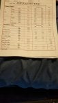

Wheel alignment settings for Mk1 TT (quattro + FWD)

These are the correct settings for a 225 + V6 TT quattro + FWD including sport suspension:
Front Toe at each wheel ................. +4' +/-3.5' (i.e. slight toe in to nearly parall)
Front camber................................... -45'+/-30' (i.e. -15' to -1° 15') [-58' +/-30' sport]
Max camber diff left to right............ 30'
Toe out on turns at 20° steering..... 1° 31' +/-20'
Castor angle (not adjustable) ........ +7° 58' [+8° 15' sport]
Max castor diff left to right ............. 30'
Rear camber .................................... (see table for quattro) {-2° +/-20' FWD}
Max camber diff left to right ............ 20'
Rear toe .......................................... +7.5' +7.5'/-5' (i.e. +2.5' to +15') {+14' [+19.5' sport] +/-5' FWD}

The above table of camber and height really only serves to check your suspension is not worn or bent. Setting a height will give a certain camber and there is little scope for adjustment without fitting adjustable tie bars. The factory manual suggests slight adjustment is possible by loosening the tie bar bolts and using the small amount of play but adjustment is minimal and requires replacement stretch bolts and straps to heave the wheel into position. Adjustable tie bars make the job of adjustment much easier.
Having more negative camber on the rear suspension will tend to give you more grip on cornering but will tend to increase tyre wear slightly. A good set up may only mean that your rear tyre inside edges become bald when the rest of the tyre needs replacing anyway so may not be an issue. -2° 10' or so is not usually a problem. Over 3° may be. Reducing the rear camber angle with adjustable tie bars can remove the inside edge wear characteristic of negative camber but will reduce rear grip on cornering with possible unexpected over steer if pushed on cornering with a "fork lift truck" tendency.
Toe being set incorrectly wears tyres fastest. The front has a huge adjustment range and if set incorrectly will show up with worn inside or outside edges which can wear to the canvas within a few hundred miles when the rest of the tyre has plenty of tread so can ruin a pair of good tyres very quickly.
For the rear, incorrect toe can be a little deceptive. There is only a small adjustment range so wear can not be as rapid as the front. Too much toe-in will cause outer edge wear usually but with a large amount of negative camber on the rear the tyres will tend to scrub across the whole surface giving the appearance of correct wear pattern but accelerated wear - perhaps halving a tyres life. The toe error and camber tend to offset each other's tell tale characteristic. The sideways scrub causes the tread blocks to become feathered however - you can feel sharp edges with the palm of your hand flat on the tread in one direction (facing in) as a check. Correctly set up there should be no scrub due to excessive toe in - the tread blocks will feel to have blunt edges (not sharp in one direction) but the inside edge will naturally wear quickest because of camber - however this should only be noticeable at the end of the tyre's life.
Uneven toe at the rear causes a non zero "thrust angle" and will cause the car to rear wheel steer to one side making the driver steer slightly in the opposite direction to compensate and maintain a straight ahead direction. This causes the car to "crab" slightly and can cause inside front edge tyre wear due to the off centre steering rack position and the inbuilt cornering geometry where the inside wheel follows a tighter cornering radius - effectively giving toe out (negative toe). The steering wheel will need turning to one side all the time which is the obvious symptom of rear toe being uneven giving a thrust to one side.
Setting front camber:

Set front camber first as this also radically affects front toe. The three nuts (shown above) under the ball joint should be loosened allowing the studs free to move in the slots of the Track Control Arm. Straps to pull the wheel, or a special tool that pulls on one of the studs is required to stop the camber sliding to maximum setting. Nuts should be set to 75 Nm (clean serrations or use new nuts). If equal camber can not be set it's sometimes possible to shift the sub frame over in order to balance. Twisting the sub frame can also balance caster which is otherwise not adjustable.
Setting front toe:
Front toe should be set after camber. Both left and right toe must be adjusted and set correctly with the steering wheel in the straight ahead position. Failure to keep the steering wheel straight can upset the zero setting of the ESP angle sensor. Under no circumstances should the steering wheel be removed to correct a left right toe imbalance - toe must be set correctly for each side.

To do this counterhold the ball joint (A) and loosen the locknut (B). Turning the tie rod (C) will alter toe. Make sure the rack gaiter is not twisted. If the adjustment is seized with corrosion, heating up the locknut with a butane blow torch will unseize it if WD40 fails. A wet rag can be used to protect vulnerable items. Re-check setting after tightening locknut to 50 Nm.
Setting rear camber and toe
Rear camber is not normally easily adjustable unless adjustable tie bars are fitted but rear toe can be adjusted relatively easily. If camber can be adjusted it should be adjusted before toe is attempted. To adjust rear toe loosen the four bolts on the trailing arm front bush mounting and tap the mounting plate either way with a mallet. Tighhten bolts to 75 Nm (clean serrations or replace). Toe should be set equally to maintain straight driving of the vehicke with no left right bias (zero thrust angle).

Rear camber depends on suspension height but camber is probably best set to between -1.5° (less wear but less grip) and -2.5° (good grip slight inner edge wear) but around -3° or over may give excess tyre wear on the inner edge but probably better track performance.
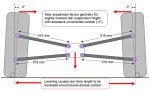
When lowering causes excess camber, it's often not possible to achieve correct toe. Excessive toe in (positive toe) normally causes outer edge tyre wear and excess negative camber (wheels lean in) normally causes inner edge wear but the combination of both these excesses can actually cause even but more rapid rear tyre wear across the whole tyre tread due to feathering. This is often the case when the quattro rear geometry is set to a compromise which includes excess toe in.
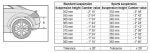
Camber and toe are also interrelated on this suspension setup and here's why:

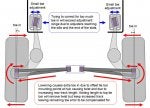
As the rear track is increased (wheel contact point with road moved further apart), then because of the rear trailing arm arrangement there is a tendancy to toe in - the front trailing arm pivot points should ideally be moved further apart to compensate. There are slotted mounting brackets here to allow for a limited toe adjustment. However there is another effect on toe. The tie bar mounting points at the hub are offset to the vertical - the top bar hub bushes are slightly forward and the rear bar bushes slightly to the rear of the hub. As the bottom arm pushes out and the top arm pulls in, when lowering, a twist is imposed on the bub which also increases toe in as well as extra negative camber.

Adjustable tie bars can be fitted into the upper or lower tie bar position and can compensate for the twist at the hub due to the bush offset but in order to achieve less camber, either the top bars will have to lengthen or the bottom bars shorten. Because the bottom bars have already pushed the wheels further apart when lowering, an adjustable top bar fitment will also have to push the wheels further apart to give less camber and this is when you may run out of toe adjustment at the trailing arm front mount slots. They can't go further out than the sills. Fitting the adjustable bars to the lower arm position has the advantage that not only can it correct camber but by pulling the wheels back in towards each other the toe adjustments are then less likely to hit the sills and run out of adjustment.

(Note: -1.5° camber shown for illustrative purposes only)
Of course if you lower even more you may run out of toe adjustment the other way and your adjustable tie bars may not shorten enough even if you do take the lock washers off (the right hand lockwasher is useless with the left hand thread anyway). Another trick is to take the shorter original top bars (515 mm) and fit them in the lower position and then fit your adjustable tie bars in the upper position and make them longer to compensate. This can then centre the toe adjustment slots for you.
It all depends on how much you lower and what camber you want to have but it should be possible to avoid using eccentric or offset bushes either at the end of the tie bars or the front of the trailing arms which is less than ideal.
From Etka:
1999 225 TT quattro (pre facelift):
1J0 505 232 L - Rear track control arm upper
1J0 505 232 N - Rear track control arm lower
1J0 505 223 M - Left swing arm
1J0 505 224 M - Right swing arm
1J0 505 235 F - Rear subframe
2006 225 TT quattro (post facelift):
1J0 505 232 L - Rear track control arm upper
1J0 505 232 N - Rear track control arm lower
1J0 505 223 M - Left swing arm
1J0 505 224 M - Right swing arm
1J0 505 235 F - Rear subframe
As you can see, both early and later TTs had the same tie bars but in both cases upper and lower are different. I measured my (pre facelift) upper bars at 515 mm between centres and lower 519 mm. There is some play in the holes which allows for some adjustment and I believe later manufactured arms had slightly elongated outer holes to allow even more adjustment.
The difference in camber between pre and post facelift, at the same ride height where the table overlaps, is almost identical with only two minutes difference which could easily be a measurement error and certainly encompassed by the play in the bolt holes.
Height - 352 mm . . . -2° 10' (pre) . . . -2° 08' (post)
Height - 355 mm . . . -2° 04' (pre) . . . -2° 02' (post)
Height - 360 mm . . . -1° 54' (pre) . . . -1° 52' (post)
Track Control Arm failure
The arms have been known to snap at the hub end causing sudden massive camber and corner lowering. This is due to the original rose bushes going rusty and partially seizing, causing a repeated bending moment to be applied to the end of the arm with inevitable fatigue crack propagation and sudden failure, usually over a bump or pot hole. Just replacing the broken arm is not going to fix the cause - check the bush.
Replacement revised bushes are a double rubber bonded concentric tube design, which don't seize. It's important that these bushes are tightened with the full weight of the car on the wheels, with the normal rest position of the suspension set, so as not to pre twist the bush which will shorten its life. It's also important that replacement is done in top or bottom pairs for left-right symetry of suspension compliance.
When adjusting or replacing bushes or arms use new nuts and bolts, as they are stretch bolts and weaken each time they are torqued and tightened to specification, resulting in less pre-load clamping force.
1J0 505 203 - Bonded rubber bush
N 104 162 01 - M12 x 1.5 x 75 bolt (outer hub end)
N 104 280 01 - M12 x 1.5 x 80 bolt (inner diff end)
N 101 064 02 - M12 shouldered self locking nut
Tightening specification: 70 Nm + 90° (quarter turn)
These are the correct settings for a 225 + V6 TT quattro + FWD including sport suspension:
Front Toe at each wheel ................. +4' +/-3.5' (i.e. slight toe in to nearly parall)
Front camber................................... -45'+/-30' (i.e. -15' to -1° 15') [-58' +/-30' sport]
Max camber diff left to right............ 30'
Toe out on turns at 20° steering..... 1° 31' +/-20'
Castor angle (not adjustable) ........ +7° 58' [+8° 15' sport]
Max castor diff left to right ............. 30'
Rear camber .................................... (see table for quattro) {-2° +/-20' FWD}
Max camber diff left to right ............ 20'
Rear toe .......................................... +7.5' +7.5'/-5' (i.e. +2.5' to +15') {+14' [+19.5' sport] +/-5' FWD}
The above table of camber and height really only serves to check your suspension is not worn or bent. Setting a height will give a certain camber and there is little scope for adjustment without fitting adjustable tie bars. The factory manual suggests slight adjustment is possible by loosening the tie bar bolts and using the small amount of play but adjustment is minimal and requires replacement stretch bolts and straps to heave the wheel into position. Adjustable tie bars make the job of adjustment much easier.
Having more negative camber on the rear suspension will tend to give you more grip on cornering but will tend to increase tyre wear slightly. A good set up may only mean that your rear tyre inside edges become bald when the rest of the tyre needs replacing anyway so may not be an issue. -2° 10' or so is not usually a problem. Over 3° may be. Reducing the rear camber angle with adjustable tie bars can remove the inside edge wear characteristic of negative camber but will reduce rear grip on cornering with possible unexpected over steer if pushed on cornering with a "fork lift truck" tendency.
Toe being set incorrectly wears tyres fastest. The front has a huge adjustment range and if set incorrectly will show up with worn inside or outside edges which can wear to the canvas within a few hundred miles when the rest of the tyre has plenty of tread so can ruin a pair of good tyres very quickly.
For the rear, incorrect toe can be a little deceptive. There is only a small adjustment range so wear can not be as rapid as the front. Too much toe-in will cause outer edge wear usually but with a large amount of negative camber on the rear the tyres will tend to scrub across the whole surface giving the appearance of correct wear pattern but accelerated wear - perhaps halving a tyres life. The toe error and camber tend to offset each other's tell tale characteristic. The sideways scrub causes the tread blocks to become feathered however - you can feel sharp edges with the palm of your hand flat on the tread in one direction (facing in) as a check. Correctly set up there should be no scrub due to excessive toe in - the tread blocks will feel to have blunt edges (not sharp in one direction) but the inside edge will naturally wear quickest because of camber - however this should only be noticeable at the end of the tyre's life.
Uneven toe at the rear causes a non zero "thrust angle" and will cause the car to rear wheel steer to one side making the driver steer slightly in the opposite direction to compensate and maintain a straight ahead direction. This causes the car to "crab" slightly and can cause inside front edge tyre wear due to the off centre steering rack position and the inbuilt cornering geometry where the inside wheel follows a tighter cornering radius - effectively giving toe out (negative toe). The steering wheel will need turning to one side all the time which is the obvious symptom of rear toe being uneven giving a thrust to one side.
Setting front camber:
Set front camber first as this also radically affects front toe. The three nuts (shown above) under the ball joint should be loosened allowing the studs free to move in the slots of the Track Control Arm. Straps to pull the wheel, or a special tool that pulls on one of the studs is required to stop the camber sliding to maximum setting. Nuts should be set to 75 Nm (clean serrations or use new nuts). If equal camber can not be set it's sometimes possible to shift the sub frame over in order to balance. Twisting the sub frame can also balance caster which is otherwise not adjustable.
Setting front toe:
Front toe should be set after camber. Both left and right toe must be adjusted and set correctly with the steering wheel in the straight ahead position. Failure to keep the steering wheel straight can upset the zero setting of the ESP angle sensor. Under no circumstances should the steering wheel be removed to correct a left right toe imbalance - toe must be set correctly for each side.
To do this counterhold the ball joint (A) and loosen the locknut (B). Turning the tie rod (C) will alter toe. Make sure the rack gaiter is not twisted. If the adjustment is seized with corrosion, heating up the locknut with a butane blow torch will unseize it if WD40 fails. A wet rag can be used to protect vulnerable items. Re-check setting after tightening locknut to 50 Nm.
Setting rear camber and toe
Rear camber is not normally easily adjustable unless adjustable tie bars are fitted but rear toe can be adjusted relatively easily. If camber can be adjusted it should be adjusted before toe is attempted. To adjust rear toe loosen the four bolts on the trailing arm front bush mounting and tap the mounting plate either way with a mallet. Tighhten bolts to 75 Nm (clean serrations or replace). Toe should be set equally to maintain straight driving of the vehicke with no left right bias (zero thrust angle).
Rear camber depends on suspension height but camber is probably best set to between -1.5° (less wear but less grip) and -2.5° (good grip slight inner edge wear) but around -3° or over may give excess tyre wear on the inner edge but probably better track performance.
When lowering causes excess camber, it's often not possible to achieve correct toe. Excessive toe in (positive toe) normally causes outer edge tyre wear and excess negative camber (wheels lean in) normally causes inner edge wear but the combination of both these excesses can actually cause even but more rapid rear tyre wear across the whole tyre tread due to feathering. This is often the case when the quattro rear geometry is set to a compromise which includes excess toe in.
Camber and toe are also interrelated on this suspension setup and here's why:
As the rear track is increased (wheel contact point with road moved further apart), then because of the rear trailing arm arrangement there is a tendancy to toe in - the front trailing arm pivot points should ideally be moved further apart to compensate. There are slotted mounting brackets here to allow for a limited toe adjustment. However there is another effect on toe. The tie bar mounting points at the hub are offset to the vertical - the top bar hub bushes are slightly forward and the rear bar bushes slightly to the rear of the hub. As the bottom arm pushes out and the top arm pulls in, when lowering, a twist is imposed on the bub which also increases toe in as well as extra negative camber.
Adjustable tie bars can be fitted into the upper or lower tie bar position and can compensate for the twist at the hub due to the bush offset but in order to achieve less camber, either the top bars will have to lengthen or the bottom bars shorten. Because the bottom bars have already pushed the wheels further apart when lowering, an adjustable top bar fitment will also have to push the wheels further apart to give less camber and this is when you may run out of toe adjustment at the trailing arm front mount slots. They can't go further out than the sills. Fitting the adjustable bars to the lower arm position has the advantage that not only can it correct camber but by pulling the wheels back in towards each other the toe adjustments are then less likely to hit the sills and run out of adjustment.
(Note: -1.5° camber shown for illustrative purposes only)
Of course if you lower even more you may run out of toe adjustment the other way and your adjustable tie bars may not shorten enough even if you do take the lock washers off (the right hand lockwasher is useless with the left hand thread anyway). Another trick is to take the shorter original top bars (515 mm) and fit them in the lower position and then fit your adjustable tie bars in the upper position and make them longer to compensate. This can then centre the toe adjustment slots for you.
It all depends on how much you lower and what camber you want to have but it should be possible to avoid using eccentric or offset bushes either at the end of the tie bars or the front of the trailing arms which is less than ideal.
From Etka:
1999 225 TT quattro (pre facelift):
1J0 505 232 L - Rear track control arm upper
1J0 505 232 N - Rear track control arm lower
1J0 505 223 M - Left swing arm
1J0 505 224 M - Right swing arm
1J0 505 235 F - Rear subframe
2006 225 TT quattro (post facelift):
1J0 505 232 L - Rear track control arm upper
1J0 505 232 N - Rear track control arm lower
1J0 505 223 M - Left swing arm
1J0 505 224 M - Right swing arm
1J0 505 235 F - Rear subframe
As you can see, both early and later TTs had the same tie bars but in both cases upper and lower are different. I measured my (pre facelift) upper bars at 515 mm between centres and lower 519 mm. There is some play in the holes which allows for some adjustment and I believe later manufactured arms had slightly elongated outer holes to allow even more adjustment.
The difference in camber between pre and post facelift, at the same ride height where the table overlaps, is almost identical with only two minutes difference which could easily be a measurement error and certainly encompassed by the play in the bolt holes.
Height - 352 mm . . . -2° 10' (pre) . . . -2° 08' (post)
Height - 355 mm . . . -2° 04' (pre) . . . -2° 02' (post)
Height - 360 mm . . . -1° 54' (pre) . . . -1° 52' (post)
Track Control Arm failure
The arms have been known to snap at the hub end causing sudden massive camber and corner lowering. This is due to the original rose bushes going rusty and partially seizing, causing a repeated bending moment to be applied to the end of the arm with inevitable fatigue crack propagation and sudden failure, usually over a bump or pot hole. Just replacing the broken arm is not going to fix the cause - check the bush.
Replacement revised bushes are a double rubber bonded concentric tube design, which don't seize. It's important that these bushes are tightened with the full weight of the car on the wheels, with the normal rest position of the suspension set, so as not to pre twist the bush which will shorten its life. It's also important that replacement is done in top or bottom pairs for left-right symetry of suspension compliance.
When adjusting or replacing bushes or arms use new nuts and bolts, as they are stretch bolts and weaken each time they are torqued and tightened to specification, resulting in less pre-load clamping force.
1J0 505 203 - Bonded rubber bush
N 104 162 01 - M12 x 1.5 x 75 bolt (outer hub end)
N 104 280 01 - M12 x 1.5 x 80 bolt (inner diff end)
N 101 064 02 - M12 shouldered self locking nut
Tightening specification: 70 Nm + 90° (quarter turn)


")