Audi TT Forum banner

How to - Installation for 1701 Bluetooth Streaming Box for RNS-E

6.8K views 18 replies 5 participants last post by  SwissJetPilot  
#1 ·
My intended purpose for this project was primarily to provide a means to charge my phone. Obviously I can use it for making hands-free calls via Bluetooth but you can imagine the futility of trying to have a conversation on the autobahn with the top down.

I had initially considered installing a 12V-USB port under the center console with a charging cable routed into the center tray. But I don't want to have to worry about my phone being left unattended when the top is down and I go in to pay for gas. Also, in just normal driving, leaving the phone in the sun is not doing it any favors either. So keeping it in the glove box, out of sight and sun, made more sense.

I don't use the CD changer anyway so getting a bit more storage space was an added benefit. And I don't intend using the BT-1701 USB port to provide music to the RNS-E since I keep all my music on SD-cards, but I'll have to try it and see how that feature actually works.

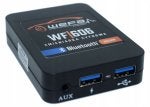
Bluetooth Streaming Box 1701 (USBN17) from USB-Nachruesten.de.

For reference, my 2007 Roadster was fitted with the following equipment -
  • RNS-E (192)
  • 6-CD Changer in the Glove Box
  • Bose Sound System and Amp
  • OEM Phone kit in center tray (since removed)
  • No AUX connection in the center console
  • 32-Pin connector supporting video box for my reverse camera
Suggested tools

• VAG head unit removal keys (x4)​
• Small flat screw driver​
• Small Philips screw driver​
• Electrical cloth tape​
• Small cable ties​
• Connector de-pinning tool​

Project Quick Links

1. CD Changer Removal
2. Case Prep
3. RNS-E Removal
4. BT-1701 Installation, Set-up and Test
5. Tips and Tricks for Installation
6. Connecting Cables and Final Installation


As delivered from USB Nachruesten -
Image

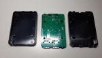
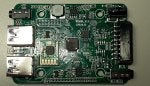
Bits inside the package -
Image


The case shown here on the LLLParts website, is item #5 Part Number: 8P0035113. You can find it on Amazon and eBay for around €25 - 35. I bought mine directly from Audi Parts for less than €20, so why buy it from a re-seller?
Image

Image


Installation instructions are attached here for reference. Be sure to download the latest instructions from their website in the event there have been any changes or updates -

.
 

Attachments

#2 ·
1. CD Changer Removal

• Turn on the ignition and press the eject button to make sure there are no CDs left inside.
• Turn the ignition off and remove the key
• Insert the two release keys into the slots, note the orientation, and it pull straight out.
• You have to disconnect the cable blind as you can't pull the unit out far enough to see it. Just press on the outer release tabs and it disconnects easily.

At this point, the CD Changer connector harness will be loose. You can either use a small cable tie or cloth electrical tape to secure it somewhere behind the case to keep it out of the way and from rattling against something.

NOTE - Do not install the new cse until after you have done the cable routing. There are two large retention clips on either side of the case which make its removal very difficult once it has been installed.

Image
Image
Image
Image
Image
 
#3 ·
Wow that was fast, didn't you order it like a day ago? lol

Nice though. You wouldn't believe what a hard time I had removing the AMI from the glovebox to put my (similar BT thing) in. I didn't need to remove it but I had previously just had it behind the dash where I obviously couldn't access the USB and AUX ports.

I've never even used those ports lol, but just to have them accessible I had to wire it through the AMI tray to get into the glovebox. Problem is, even with the glovebox removed, there's really no way to get into that rubber/plastic AMI tray, even trying to snake a wire though there's not enough room--you have to remove the tray and cut a small notch in the back of the tray. Getting the AMI unit to release is supposed to go the same way as anything else in there--use the radio removal keys and out it pops, right? Well in my case--wrong! :mad: One of the clips inside instead got bent up and it would. Not. Release. I had to really mangle it from the other side (glovebox removed) and basically force it out, which was real nice. After many expletives issued to "these German clowns and their clips"🤣 I finally got it out. It's back in now with the wire coming through nicely and the thingy sitting in the AMI tray, but can't get those metal clips separate so it's only being held in by the one now or whatever.
 
#4 ·
@ TT'sRevenge - Sometimes the keys are not cut properly and don't engage with the release clips. I had to use a very small file to enlarge the notch in one of the keys I received. I also found for the RNS-E, if you use two socket extensions, and run them vertically through the holes the the keys, you can engage both sides at the same time and it's a lot easier to pull the head unit out.

And of course with the CD player missing I now have a fault in two different Addresses. I'll have to update the long code and delete the CD Changer.

Address 37: Navigation
00857 - CD Changer Unit (R41)​
004 - No Signal/Communication​

Address 56: Radio
00857 - CD Changer Unit (R41)​
004 - No Signal/Communication​
 
#6 ·
The new case arrived and as you can see the depth of the case is a full third less than the depth of the CD unit. :(

Image

Image

While the BT-1701 adapter fits inside the case quite easily, my phone (which is 15cm long) sticks out a bit. Fitting the phone in sideways work, but I still have to content with the connectors so it gets a bit tight in there. I guess I could just go with the BT-1701 mounted inside the case and leave the phone in the glove box, but then it's one more thing in the glove box. I was hoping to fit both in the case.
Image

As shown here, depending on the size of your Smartphone (and orientation), it may extend past the edge of the case -
Image


Couple of thoughts: :unsure:

Option 1 - The BT1701 goes somewhere behind the glovebox and I mount a standard VAG USB/AUX port into the back of the unit. Then I would have to build a couple of connectors to connect the two together. This would free up some needed space inside the box however I would still need two more connectors to connect from the USB/AUX port to my phone.

• Pros - Looks professional. Gain space in the box.

• Cons - Making a connector between the BT1701 and USB/AUX will be a PITA. Extra cost for wires and connectors. Loss of the power USB in the BT1701. Still need another set of connections between the USB/AUX port and the phone. The USB/AUX is not easy to reach.
Image

Option 2 - The BT1701 goes somewhere behind the glovebox and I just run AUX and USB extension cables directly from the BT-1701 into the box.

• Pros - Cheap and easy installation. Gain space in the box. Longer connectors are easier to access when connecting to the phone. Less parts required. Can take advantage of all three ports (AUX, power and USB) in the BT1701.

• Cons - Doesn't look "factory". Will need to secure the connectors to the BT-1701 so they can never come loose.
Image
 
#9 ·
Recently done option 1 with the data port from aftermarket head unit. It almost appears oem but if I am completely honest Swiss it’s a PITA if trying to plug a lead in. This is why the lead is still plugged in although I plan on attaching a drive to it later on. The space is just tight to get to the port from drivers seat. Which you have probably vaguely tested with the box in your hand like I did. I still went with it though as it freed the area from the redundant 30pin apple port it had and gave me a place for the other usb port from head unit.
Image
 
#10 ·
@ Nidana - Trying to get my fingers all the way to the back of the case in order to plug in the cables is a bit of a challenge. And the hassle of the additional connectors is making me lean towards Option B. Also so when my wife is with me she can charge her phone on the additional USB power port. There should be space for two phones if the BT unit is mounted to the top of the case.

For passing the cables through the back of the case, I was looking at the grommets on the back of my PC tower. It's large enough to accommodate the USB connectors, so I can easily get all three cables through this opening.
Image


Or I could Dremmel open the connector port on the back of the box and run everything through that rather than adding another big hole in the back.

Image
 
#12 ·
2. Case Preparation

I've decided that the BT-1701 unit will be positioned in the upper left side of the case (closest to driver in LHD) so it's easy to reach.

I cut an opening in the back of the case just large enough for the BT-1701 to partially stick out the back. This will provide support to the unit so can't move or rattle around. Additionally, it will be held in place to the top of the case using a strip of double-sided automotive trim adhesive tape. If ever have to remove the glovebox, it will be easier to remove the BT-1710 in order to access the connector and mic cables.

I removed the unused connector mounts on the back of the case in order to put a strip cloth electrical tape over holes. They're out of sight when installed so it's not really an issue.

NOTE - The BT-1701 should only be installed into the case AFTER you have routed the cables and performed a test that the system works.

Image
Image

Image


Here you can see the BT mounted to top of the case with two phones placed side by side. This position makes it easy to reach when plugging in the USB and/or Aux.
Even with two phones inside, there's still room for a MP3 player which can be connected via the AUX port. The USB-C connector shown here is 20mm long.

Image

.
 
#14 ·
3. RNS-E Removal

Tools required:


• 4x Head Unit Release Keys *VAG Radio Removal Tool (-T10057-)​
• Small flat and Philips screwdrivers​

Note: This installation uses an early 2007 Model 192 RNS-E. The connections and set up may be slightly different for the Model 193 RNS-E.

Additional information on removing the RNS-E and other radio and sound systems can be found in the Workshop Manual, Communication - D3E8006B7D9 located here.

Disclaimer: These instructions are for demonstration and educational purposes only. The actual use of these instructions are done so at your own risk. Installation should only be done by qualified Audio technicians or by persons familiar with which end of a screwdriver to use.

Warning: The passenger airbag light assembly can be removed without disconnecting the power connector. If the power connector is disconnected and power is applied, this will result in a fault which will require an OBDII diagnostic device to clear and reset.

RNS-E Removal -

The ignition is off and the key is removed from the ignition.

Anytime a head unit (HU) is removed or installed it's a good idea use a couple of heavy towels folded over several times and placed on top of the shifter and HVAC controls. This will protect the surrounding surfaces and provide a bit of support for the HU which will make removing the connectors easier.

Vehicles with a manual transmission can move the shifter to 2nd or 4th to get a bit more room under the HU.

Place a heavy towel over the shifter to protect contact with the metal case.
Image

When the four release keys are inserted, there should be an audible "click" as each key fits into place. There will be some resistance when pulling the HU out, so some gentle persuasion will be required. Pulling just a bit at a time on each key should help it come out easily enough. Once out the release keys can be removed since they are no longer required.

RNS-E pulled out of the dash. The keys can be removed by depressing the catches.
Image


Some keys will be marked L and R. Insert the key until a click is heard.To remove, press the side of the retaining clip on the case and withdraw the key.
Image


Removing the RNS-E Cables and Passenger Air Bag Light Assembly -

The RNS-E is carefully pulled out as far as possible. Caution is used to avoid putting undo stress on the cables. All four cable connectors, and the airbag passenger light, must be disconnected in order to remove the RNS-E from the dashboard.

I find it easier to start with the blue GPS and the grey 32-pin multi connectors first since they are both up high on the back of the RNS-E and easy to reach. Once those two are out of the way the white ZF Frequency connector can be removed with the the Quadlock being removed last.

• GPS Farak connector (blue) top right corner​
• 32-Pin multi connector (if present)​
• ZF Frequency Farak connector (white) bottom left corner (may have two cables).​
• Quadlock​

The GPS and ZF connectors have push-to-release tabs. Since they are keyed (they can not be rotated) so they will take some effort to pull off even with the release tab firmly pressed.
Image


The gray 32-pin multi connector has a pink locking lever.
Depress the tab on top of the connector (red arrow) to release the pink lever and rotate the lever to disconnect the connector.

Image


The Quadlock has release tab at the bottom of the lever. Press the release tab first then pull the locking lever upwards. Once free, you can pull the connector straight out.

To release the Quadlock (1) Press the release tab and (2) Lift the latch upwards towards the top of the HU. The connector will come loose and can be pulled straight out.
Image


Once the cables are are all out of the way, the passenger airbag light assembly can be removed. Disconnecting the passenger air bag light assembly is done by reaching inside the facia and below the RNSE. The two metal tabs on either side are pressed down while simultaneously pushing entire assembly outwards through the front facia.

Alternately, the connector can be removed by depressing the small metal locking tab.

WARNING - If the passenger air bag light power connector is disconnected DO NOT TURN ON THE IGNITION! If the power cable is removed from the air bag light assembly and the ignition is turned on, a fault code will be reported which can only be reset with an OBDII diagnostic tool.


Press the metal tabs on either side of the passenger air bag light assembly and push it forward, out of the facia.
Image

To remove the connector without removing the assembly, the connector can be shimmed with a 6mm wide piece of old credit card to release it from the connector -
Image


With the RNS-E out of the way, you can now start to install the case and BT-1701.
Image
 
#15 ·
4. BT-1701 Installation, Set-up and Test

It's a good idea to perform system test before installing everything.

UPDATE - After the installation, I discovered there's no Bose-pin connector in the BT-1701 harness. This means with the blue B-Connector removed from the system, the Bose Amp will not function properly. This will cause a noticeable change in the bass and also the volume will increase. To avoid this, you can remove the Bose-pin (brown wire #7) from the B-Connector and plug it into the BT-1701 pin #7 position. Link here.

Bose-pin removed from the blue B-Connector and inserted into the BT-1701 white connector, #7 position -
Image


The blue B-Connector is removed by pressing the retention tab and pulling the connector out of the Quadlock. It may be necessary to move the Quadlock locking lever back towards the locked position as may be in the way when the B-Connector is removed. A small flat-blade screwdriver can be used to press the B-Connector release tab.

Image


With the blue B-Connector removed, the white connector from the BT-1701 cable can be inserted and fully seated into the Quadlock. The face of the Quadlock should be visually inspected to ensure the white and green connectors are flush.

The BT-1701 ground wire connected to the RNS-E case using one of the existing Philips-head screws.
Image


Testing the RNS-E and BT-1701 Connection & Connectivity -

The the BT-7101 connector cable and microphone cable are now plugged into the back of the BT-1701 unit. The green C-Connector will provide power and ground to for both the RNS-E and BT-1701. Therefore it is not necessary to connect the other three cables into the RNS-E to perform this test.

WARNING! The passenger airbag power cable must be connected before applying power.

The Quadlock is secured to the RNS-E. The ignition key is inserted and the ignition is switched to ACC. The RNS-E is turned on.

Select CD/TV > Source > CD Changer. Once this is done, the blue LED light in the BT-1701 should come on.

Image


Trouble shooting when the blue LED doesn't come on -

The RNS-E and the ignition must be turned off first!

• Check all connectors and connections at the RNS-E and BT-1701 are properly seated.
• Check the ground connection.
• Selected the CD-Changer and not CD-drive.

Note - The BT-1701 installation and test instructions should be referenced.

Image


Pairing the BT-1701 to a Smartphone -

When the blue LED light comes on, the BT-1701 is now functional and can be paired to a Smartphone using the manufactures paring protocol. The Samsung Galaxy paring protocol is shown below.

With the microphone plugged into the back of the BT-1701 a call can be made from the Smartphone. The ring tone should be heard over the speakers. When the call is connected, the voice of the person receiving the call should be heard over the speakers. If the listener can not hear you very well, you may need to reconsider the location of the microphone.

Bluetooth pairing protocol for the Samsung smart phone.
Image


Completing the Installation -

If the connection and connectivity between the RNS-E, BT-1701 and Smartphone is successful the next steps can be taken to complete the installation:

• Route the cable from the BT-1701 to the RNS-E,
• Fitment of the BT-1701 into the glove box.
• Route the microphone to the best suitable location.
• Reinstall the RNS-E
- Reinstall the passenger air bag light assembly.​
- Cables are are re-connected and verified.​
- The RNS-E is pushed back into the dash and secured.​
It's possible that during the testing with the other connectors removed, faults may be present. An OBDII diagnostic device can be used to scan and clear any related faults. You may also want to change the long code to remove the CD-Changer.

After routing the microphone to the steering column, I used automotive cloth tape to connect the microphone cable to the BT-1701 cable. This way when routing the cable into the glove box, the microphone cable is routed together with the main cable.
Image


BT-1701 main cable and the microphone cable have been routed from the RNS-E side into the back of the glove box.
Image
 
#16 ·
5. Tips and Tricks for Installation -

I wanted to understand why the Passenger Air Bag Light Assembly (PABLA) is such a PITA to remove, and discovered there is a trick to removing it. You first get one clip released by pressing on it from the side, and at the same time, push on the back of it from that side, this tends to bind the clip and keep it depressed so you can do the same for the other side. Repeat the process for the other clip. I found by repeating the process from one side to the other, the PABLA will come out. It's a very tight fit and it takes a bit or pressure to remove it.

Image


Shown in closer detail, once the leading edge of the tab is under the plastic keepers and pressure is applied on that same side, it will tend to remain in this position. Repeat this process on the other side for the other tab, working back and forth while also pushing the PABLA out of the fascia.
Image


Also shown in closer detail, is the PABLA power connector. I first tried to release the little metal tab where it comes up in the square hole in the PABLA body. Despite using a number of small tools, I realized the little metal tab can't really be pressed down due to the design.

Image


However it turns out can be shimmed and that worked quite well. I used an old hotel plastic key which is about 1mm thick and cut it to 6mm in width and long enough to make handling easy. It was then inserted it into the space where the tab is located. By pushing the shim and the connector inwards, and then pulling both out together, this prevents the tab from catching in the square retention hole and the connector slides out. This actually worked better than I expected.
Image


Should you ever need to replace it, it's called a Harness Pigtail Plug Connector 2 Port 2 Wire. Part number 4B0-972-623
Image
 
#17 ·
Depinning Quadlock B&C Block Connectors

Depinning a VAG connector isn't that difficult, but it's a lot easier with the right tools. This set of three de-pinning tools can be found on Amazon and are very inexpensive. I found these three were adequate for the jobs at hand.

In the image below, I was used the depinning tools to de-pin the wires that came with the replacement tail light connector. The three tools shown here are intended for VAG connectors and the one with the single "finger" works well to depress the retaining barbs found on smaller terminals inside the Quadlock B and C connectors.

NOTE - For this discussion, I will explain how to de-pin the 12-pin connectors found in the Quadlock. The process is identical for both the green or blue connectors.
Image

Before you start depinning, be sure you have selected the correct terminal wire. The position numbers are indicated on the RNS-E label and embossed on the end of of the connector -
Image

Image

Start by removing the connector from the Quadlock by depressing the release tab and pulling the connector out of the Quadlock
Image

Once the connector is out, you'll need to remove the black inner connector from the outer blue or green connector. Simply release the inner tab and the black inner connector slides out. Both the blue and green connectors work exactly the same way.
Image

Once the black inner connector has been removed from the green outer connector, you can now start to de-pin the terminals.
Image

You'll need to look carefully where the retaining barb is located (these terminals/pins only have one) and to make sure the tool you use can keep the barb (red arrow) pressed down and keep it depressed past the blue arrow so you can push the pin out in the direction of the green arrow.

To release the terminal from the connector, slide the depinning tool into the connector in the direction of the green arrow and depress the barb at the red arrow. As you carefully pull the wire out from the opposite side, continue to push the tool into the connector to prevent the barb popping up and catching with the connector at the blue arrow. Failing to do so and forcing the terminal out of the connector may damage it when attempting pull it out. If the barb is properly depressed, the wire will slide out quite easily.
Image
 
#18 ·
Just some shots of what's inside the BT-1710. With the label removed, you can access the four screws that hold the case together. The main processor chip in the center is a MVSilicon ARM8064 which you can read about here. Seems this another no-name Chinese device that is simply rebranded by anyone who wants to put their name on it.
 

Attachments

#19 ·
6. Connecting Cables and Final Installation -

With the case prepped and BT-1710 test fitted, it's time for the final installation.

For the sake of an easy installation, the mic was mounted on the steering column slightly to the left so it's not visible when looking at the instrument panel. The microphone cable ran up under the knee panel (which was removed for ease of access), behind the RNS-E and into the glove box.

With the case still outside of the glove box, the BT-1701 cable (and mic connector) were pushed through the opening in the back of the glove box. The connector and mic were plugged into the BT-1701, secured in place, and then the case was pushed into the glove box. As I mentioned previously, you don't want to push the case into the glove box until you are sure everything is set up and tested first as it will be difficult to remove later.

The RNS-E cables were reconnected, paying attention to add the BT-1701 ground cable to one of the chassis screws. Once the ground wire is secured, the RNS-E was pushed back into position.

1. BT-1701 ground wire to RNS-E chassis​
2. 32-pin connector​
3. Quadlock with the BT-1701 in the B-connector position. The blue B-connector just hangs loose so it can always be reconnected if the CD changer is ever reinstalled.​
4. Passenger Air Bag Light connector​
5. FZ connector​
6. GPS connector​

Job done. :)

Image

BT-1701 and microphone connectors passed through the case. NOTE - the case is not fully inserted into the glove box yet -
Image

With the BT-1701 connected and secured to the inside of the case, the case can now be pushed into position -
Image

To provide power to my phone, I used a short 20mm USB connector -
Image

Be sure the position of the mic does not interfere with the max in-out, up-down steering wheel position and/or the turn indicator stalk -
Image