
OPS is Optical Parking System, which means you get a visual diagram of objects around the car. Front parking sensors and OPS were never available on the TT from the factory. Having rear parking sensors is a prerequisite for this guide. Details on retrofitting them are here, but use the information on module and canbus from this guide. A MK2 RNSE is required for OPS.
If you have a 8P0 919 475 park assist module (around 2009 onwards) this will be simpler as the powertrain canbus will already be present. I didn't, so had to wire that up.
Parts required:

Wiring
Park assist control module connector A (T16e) (16-pin)
Pin 1 > Fuse 7 in dash fuse box (5A) (positive, ignition live)
Pin 2 > Rear buzzer (H15), pin 2
Pin 3 > Fuse 5 in boot fuse box (5A) (positive, permanent live)
Pin 4 > Centre console parking aid button (see below)
Pin 6 > CAN gateway, pin 16 (orange/black) (powertrain CAN high)
Pin 8 > Earth
Pin 10 > Rear buzzer (H15), pin 1
Pin 13 > Centre console parking aid button warning lamp (see below)
Pin 15 > CAN gateway, pin 6 (orange/brown) (powertrain CAN low)
Park assist control module connector B (12-pin)
Pin 1 > All parking aid sensor pins 3 (earth)
Pin 2 > All parking aid sensor pins 1 (positive?)
Pin 3 > Front buzzer (H22), pin 2
Pin 4 > Front buzzer (H22), pin 1
Pin 5 > Front left parking aid sensor (G255), pin 2 (signal?)
Pin 6 > Front centre left parking aid sensor (G254), pin 2 (signal?)
Pin 7 > Front centre right parking aid sensor (G253), pin 2 (signal?)
Pin 8 > Front right parking aid sensor (G252), pin 2 (signal?)
Centre console buttons connector (T16b) (16-pin)
Pin 8 > Splice into pin 2 (brown) (earth)
Pin 9 > Park assist control module connector A (T16e), pin 13 (parking aid button warning lamp)
Pin 13 > Park assist control module connector A (T16e), pin 4 (parking aid button)
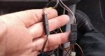
If you don't currently have a 475 module, you will need to splice into the powertrain canbus at the gateway. My blue and yellow wires can be seen in the right of this photo. They should be twisted all the way back to the parking module to avoid interference

Wires routed from module through the boot...

...and then wrapped in cloth tape and cable tied to existing wiring

Wires routed under rear bench and through centre console

The new parking sensor button (top) and my existing one (bottom). Will vary if you have TPMS and/or mag ride

Parking button wires. Notice the earth which I spliced into an existing one. Not sure why the buttons don't share an earth anyway

Parking button fitted

The is nowhere OEM to mount the front buzzer. I cable tied it to the top of the air conditioning ducting. In the A3 and R8, the front buzzer is located in this area

I poked the sensor wires through the existing firewall grommet. There are too many to easily use an existing hole (the blue one is for cruise control)

I wrapped them in cloth tape and routed them under the airbox where there are existing wires

I used a connector between the car loom and the bumper to make the bumper easier to remove and fit in future. I used a 14 pin connector but only 6 pins are required

The pins to the sensors need to be sealed as they will be exposed (the blue part)

The wires can be routed in the same way as the washer jet hose (which is under the centre grille)
I cut the sensor holes with an 18.2mm hole cutter (Sealey VS318)

Some of the double skinned part under the washer jet mounting will need to be trimmed away for the bracket to be able to mount to the external bumper cover

The straight connector sensors need to be fitted to the outer two sensors under the washer jets as otherwise there isn't space for the connector (ignore the 90 degree one in the above photo as that was a test fit before I realised)
The foam behind the bumper will need to be trimmed for the centre two sensors so that the bumper will refit properly

I roughed the surface with some sandpaper so that the sensor brackets would stick better

The finished job (before fitted fog grilles)

OPS on the RNSE

Parking buzzer settings move to the RNSE when OPS is enabled, rather than the DIS

Coding
19-CAN Gateway - Installation List
10-Park/Steer Assist - Coding
37-Navigation
Coding:
If you have a 8P0 919 475 park assist module (around 2009 onwards) this will be simpler as the powertrain canbus will already be present. I didn't, so had to wire that up.
Parts required:
Code:
4H0 919 275                      | Ultrasonic parking sensor (90 degree connector) x2
4H0 919 275 A                    | Ultrasonic parking sensor (straight connector) x2
1T0 919 133 C                    | Sensor sealing rings (satin black or grey available) x4
5J6 919 485 B                    | Skoda brackets x4

4H0 973 703                      | 3 pin connector (for sensors) x4
000 979 034 E / TE 1670146-1     | Wire set with clamp pins x6 (12 pins)
TE 1394133-1                     | Wire seals x12

8W0 972 112 A                    | 12 pin connector (brown) (for control module)
000 979 009 E / TE 144969-1      | Wire set with square pins x4 (8 pins)

8P0 919 475 H                    | Park control module (ETKA shows revisions N and Q too)

423 927 137 J 5PR                | Button (ESP, spoiler, PDC) (diff one needed for mag ride/TPMS)
000 979 009 E / TE 144969-1      | Wire set with square pins x1 (2 pins)

8E0 919 279                      | Buzzer
4B0 972 623                      | 2 pin connector (for buzzer)
000 979 009 E / TE 144969-1      | Wire set with square pins x1 (2 pins)

Wire - 0.35mm² thin wall
Wiring
Park assist control module connector A (T16e) (16-pin)
Pin 1 > Fuse 7 in dash fuse box (5A) (positive, ignition live)
Pin 2 > Rear buzzer (H15), pin 2
Pin 3 > Fuse 5 in boot fuse box (5A) (positive, permanent live)
Pin 4 > Centre console parking aid button (see below)
Pin 6 > CAN gateway, pin 16 (orange/black) (powertrain CAN high)
Pin 8 > Earth
Pin 10 > Rear buzzer (H15), pin 1
Pin 13 > Centre console parking aid button warning lamp (see below)
Pin 15 > CAN gateway, pin 6 (orange/brown) (powertrain CAN low)
Park assist control module connector B (12-pin)
Pin 1 > All parking aid sensor pins 3 (earth)
Pin 2 > All parking aid sensor pins 1 (positive?)
Pin 3 > Front buzzer (H22), pin 2
Pin 4 > Front buzzer (H22), pin 1
Pin 5 > Front left parking aid sensor (G255), pin 2 (signal?)
Pin 6 > Front centre left parking aid sensor (G254), pin 2 (signal?)
Pin 7 > Front centre right parking aid sensor (G253), pin 2 (signal?)
Pin 8 > Front right parking aid sensor (G252), pin 2 (signal?)
Centre console buttons connector (T16b) (16-pin)
Pin 8 > Splice into pin 2 (brown) (earth)
Pin 9 > Park assist control module connector A (T16e), pin 13 (parking aid button warning lamp)
Pin 13 > Park assist control module connector A (T16e), pin 4 (parking aid button)
If you don't currently have a 475 module, you will need to splice into the powertrain canbus at the gateway. My blue and yellow wires can be seen in the right of this photo. They should be twisted all the way back to the parking module to avoid interference
Wires routed from module through the boot...
...and then wrapped in cloth tape and cable tied to existing wiring
Wires routed under rear bench and through centre console
The new parking sensor button (top) and my existing one (bottom). Will vary if you have TPMS and/or mag ride
Parking button wires. Notice the earth which I spliced into an existing one. Not sure why the buttons don't share an earth anyway
Parking button fitted
The is nowhere OEM to mount the front buzzer. I cable tied it to the top of the air conditioning ducting. In the A3 and R8, the front buzzer is located in this area
I poked the sensor wires through the existing firewall grommet. There are too many to easily use an existing hole (the blue one is for cruise control)
I wrapped them in cloth tape and routed them under the airbox where there are existing wires
I used a connector between the car loom and the bumper to make the bumper easier to remove and fit in future. I used a 14 pin connector but only 6 pins are required
The pins to the sensors need to be sealed as they will be exposed (the blue part)
The wires can be routed in the same way as the washer jet hose (which is under the centre grille)
I cut the sensor holes with an 18.2mm hole cutter (Sealey VS318)
Some of the double skinned part under the washer jet mounting will need to be trimmed away for the bracket to be able to mount to the external bumper cover
The straight connector sensors need to be fitted to the outer two sensors under the washer jets as otherwise there isn't space for the connector (ignore the 90 degree one in the above photo as that was a test fit before I realised)
The foam behind the bumper will need to be trimmed for the centre two sensors so that the bumper will refit properly
I roughed the surface with some sandpaper so that the sensor brackets would stick better
The finished job (before fitted fog grilles)
OPS on the RNSE
Parking buzzer settings move to the RNSE when OPS is enabled, rather than the DIS
Coding
19-CAN Gateway - Installation List
- Enable '10 - Park/Steer Assist'[/*]
10-Park/Steer Assist - Coding
- Byte 0, bit 4 - enable 'Optical Illustration active'[/*]
37-Navigation
Coding:
- 0x?xxxx: Treble Speaker Diagnosis / Optical Parking Aid
- +2 = Optical Parking Aid installed/active[/*]
- [/*]