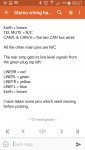
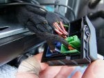
Audi TT Forum banner
61 - 80 of 86 Posts
Discussion starter · #62 ·
tttony said:
I've just pulled my HU out to check the wiring colours. Mine are as follows;

DSP EIN = green yellow. This is the one that tells the rear amp to turn on. (not blue as I said, which is Jap aftermarket HUs)
DWA = N/C
+UB = two red/white (the main pos feed)
DISENS = red/white (looped from one of the above)

Earth + brown
TEL MUTE = N/C
CAN/L & CAN/H = the two CAN bus wires

All the other main pins are N/C

The rear amp gets its line level signals from the green plug top left:

LINERR = red
LINERL = green
LINEFR = yellow
LINEFL = blue
Earth = brown

I have taken some pics which need resizing before posting.
Image


So are you saying that these are infact the 4 channels to the amp on the line in connections on your green connector. If so where does each brown wire that it is with them go ?
And is my green and yellow one the line earth ?

Thanks Tony

Sent from my SM-G900F using Tapatalk
 
ReTTro fit said:
Now after looking closer at pics
I notice the colours are twisted in pairs

Therefore it must be

1 empty

2 solid red / line FR +

3 solid brown / line FR-

4 green with yellow stripe / line gnd

5 solid brown / line RL-

6 solid green / line RL+

7 empty / empty

8 solid yellow / line FR+

9 solid brown / line FR-

10 empty / empty

11 solid brown / line RR-

12 Solid Blue / line RR+

On iPhone using Tapacrap
Yes they are mate, here's what I posted before mate

On iPhone using Tapacrap
 
Discussion starter · #64 ·
ReTTro fit said:
ReTTro fit said:
Now after looking closer at pics
I notice the colours are twisted in pairs

Therefore it must be

1 empty

2 solid red / line FR +

3 solid brown / line FR-

4 green with yellow stripe / line gnd

5 solid brown / line RL-

6 solid green / line RL+

7 empty / empty

8 solid yellow / line FR+

9 solid brown / line FR-

10 empty / empty

11 solid brown / line RR-

12 Solid Blue / line RR+

On iPhone using Tapacrap
Yes they are mate, here's what I posted before mate

On iPhone using Tapacrap
Hey Ret,

Yes but this area on the diagram has no positive and negative so if I install on the part of the quad where Tony has said what do I do with the all the negative browns there's only one input on each channel ?

Sent from my SM-G900F using Tapatalk
 
Discussion starter · #65 ·
ReTTro fit said:
ReTTro fit said:
Now after looking closer at pics
I notice the colours are twisted in pairs

Therefore it must be

1 empty

2 solid red / line FR +

3 solid brown / line FR-

4 green with yellow stripe / line gnd

5 solid brown / line RL-

6 solid green / line RL+

7 empty / empty

8 solid yellow / line FR+

9 solid brown / line FR-

10 empty / empty

11 solid brown / line RR-

12 Solid Blue / line RR+

On iPhone using Tapacrap
Yes they are mate, here's what I posted before mate

On iPhone using Tapacrap


Sent from my SM-G900F using Tapatalk
 

Attachments

I guess the grounds could be all connected together mate and connected to pin 8, line gnd

Remember that loom is going to your amp so the amp must want to see each ground

On iPhone using Tapacrap
 
Yes, I can't see it, but I Think that the four brown wires must be joined together in the loom before the plug.

The yellow/green wire should go to the DSPEIN pin to give the boot amp its turn on signal. The amp gets its 12v supply via a thicker red/green wire that is fed from a 30A fuse (fuse 35 on fuse holder C).
 
Yes, this indicates there joined
( see the very bottom line )
Image


On iPhone using Tapacrap
 
Discussion starter · #69 ·
tttony said:
Yes, I can't see it, but I Think that the four brown wires must be joined together in the loom before the plug.

The yellow/green wire should go to the DSPEIN pin to give the boot amp its turn on signal. The amp gets its 12v supply via a thicker red/green wire that is fed from a 30A fuse (fuse 35 on fuse holder C).
Jesus christ Guys we have sound!!!!
All i did was connect the green and yellow like you said and on went the amp. Thank you sooo much everyone this has been a real challenge.
I will take some pics so that anyone else with a Japanese import with a cut loom like mine can figure this out.

Thanks again

Sent from my SM-G900F using Tapatalk
 
Good man for sticking with it matey !!

Well done to tony, very knowledgable, nice one mate

On iPhone using Tapacrap
 
Discussion starter · #72 ·
tttony said:
Well done TTNZ. I'm pleased to have been able to help. I'll pop over for a quick beer sometime. LOL
Guys my hats are off to you both mi casa su casa and my beers as well :)
Ok I have one last challenge and thats moving the speaker wires to there correct homes.
Currently the sound is coming from this part in the pic below and it works but its faded wrong ie left right front and rear
Image


I need to move them to this part of the quadlock ?
Image


Problem is when I look at both of your descriptions of which wire is for which speaker they are slighty different.

Sent from my SM-G900F using Tapatalk
 
LF+ to pin 3 ( line FL )
RF+ to pin 9 ( line FR )

Join the grounds to pin 8

See if tony agrees first

On iPhone using Tapacrap
 
tttony said:
Pin 3 = blue = LINE FL
Pin5 = green = LINE RL
Pin9 = yellow = LINE FR
Pin11 = red = LINE RR
Pin8 = brown = LINE Earth
Right, this is why our pin ideas differ Tony

I totally agree on the PIN numbers mate, however

look at the pic of the plug he posted up, the Browns are in all the PIN numbers on the line outs
Image
Image


On iPhone using Tapacrap
 
TTNZ said:
Perfect thanks so much all working perfectly.

Sent from my SM-G900F using Tapatalk
So what was the final results TTNZ ?
What went where etc ?

On iPhone using Tapacrap
 
61 - 80 of 86 Posts